How is Orthoimagery Made?
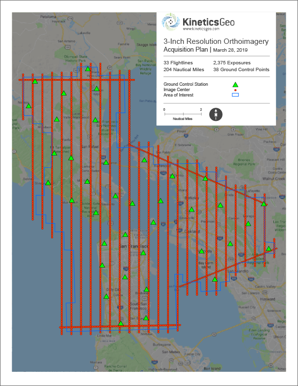
1 The first step in an orthoimagery project requires a thorough and accurate flight plan that takes into account project deliverables, historic weather conditions, and challenges such as flight-restricted areas, etc.
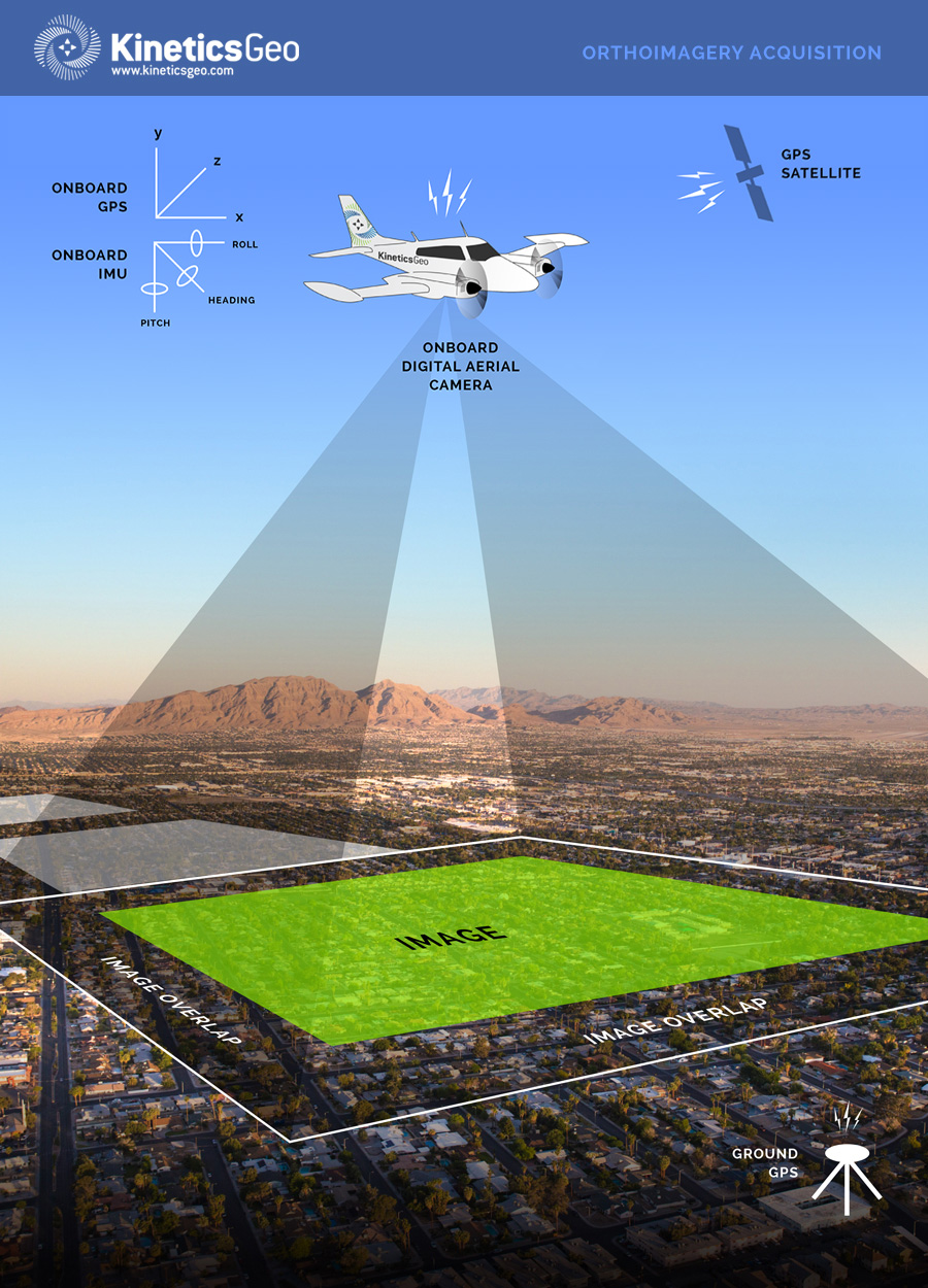
2 Based on the flight plan, flying altitude and sensor focal length, a grid of aerial imagery is acquired using a high-resolution digital aerial camera. As each image is acquired, an onboard Global Positioning System (GPS) measures the camera's exact longitude and latitude, while a ground GPS Base Station is measures from a known ground position relative to the constantly changing position of the aircraft.
3 An Inertial Measurement Unit (IMU) simultaneously measures the acceleration and rotational values of the aircraft (pitch / roll / heading). Data measured by both GPS and IMU are important for efficient imagery processing and higher accuracy, and can reduce the number of ground control survey points required for the mission / flight. In order to ensure that there are no gaps in coverage, each aerial image acquired allows for specified amounts of forward and side overlap.
4 Upon completion of the flight, GPS and IMU data are processed to generate the exterior orientation information for the acquired imagery.
5 The imagery, exterior orientation information, camera calibration, and ground control data all are ingested into a highly sophisticated Aerial Triangulation (AT) software package.
6 At every step in the ortho-mosaic process, the imagery, AT, DTM, orthorectification, and the resulting imagery mosaic product undergo rigorous quality control procedures to ensure that deliverables meet the project's required final accuracy and quality.
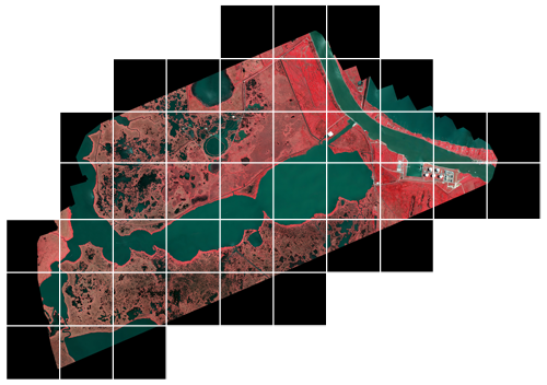
7 The orthorectified imagery is then seamlined together and color-balanced, creating a seamless, radiometrically uniform imagery mosaic for the entire project area.